洛阳松导感应加热科技有限公司
联系方式:15038554363
24小时技术热线:15038554363
邮 箱:1390003299@qq.com
厂址:河南省洛阳市洛新工业园区
中频炉怎样安装调试?
-
安装前的准备工作
安装前,必须检查所有成套装置的组成部分,炉子的主要部件及其安装材料是否齐全,并检查它们的状况。一些部件和材料因运输和保管不当而产生的缺陷,应予修复,使所有设备、部件、相应的材料及零件配套完好无缺,以确保以后的安装、调试工作的顺利进行。
除此外,对和炉子设备有关的各项土建设施进行检查验收,如核对平面布置中的主要尺寸是否正确;检查各种电气设备和主母线安装所需的基础、地沟及预埋件是否符合设计要求,炉子基础、平台标高、纵轴和横轴的偏差、地脚螺丝钉位置等是否在规定的尺寸范围之内;检查基地及平台的施工质量等是否符合要求。只有在上述准备工作完成后,才能进行炉子的安装调试工作。
二、炉子及电气设备的安装调试
-
炉体的安装
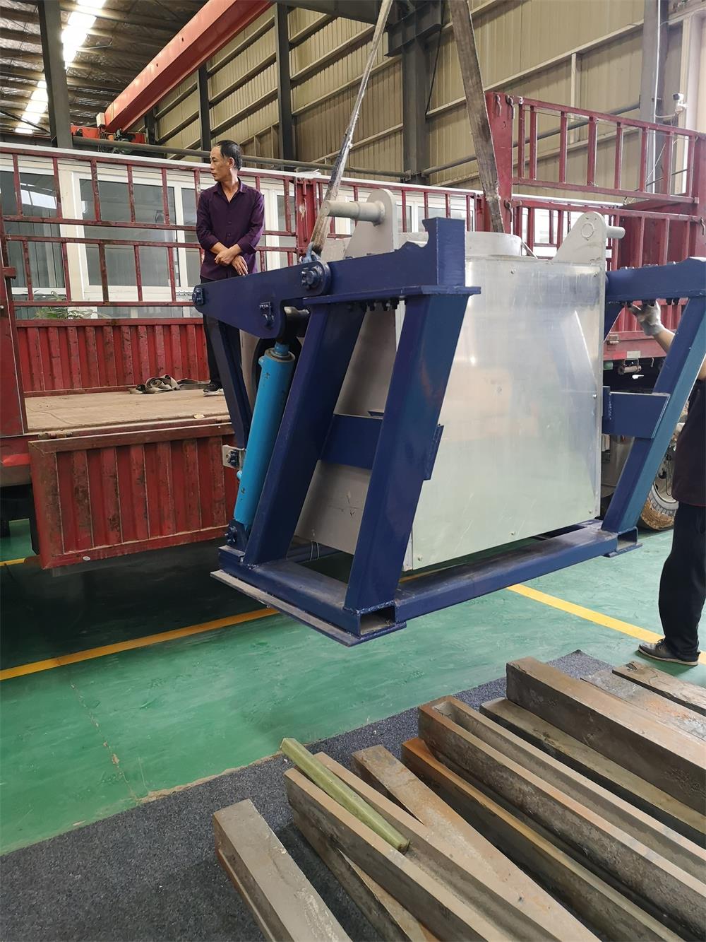
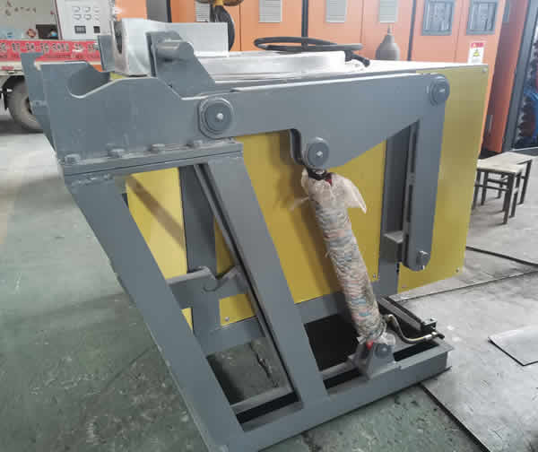
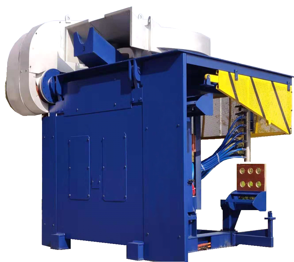
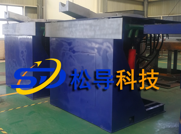
炉体的安装程序在图纸上均有规定。首先是在平的基地上安装炉架,然后安装炉油缸、炉体,如有称重装置,则应根据图纸要求安装在规定的位置上。炉子的支架(对于坩埚式中频炉包括固定支架和活动支架两部分)及炉体部分,在加工过程中,应使焊接施工造成的热变形量限制在设计的规定范围内,只有这样才能确保以后的工作顺利进行。
-
水冷系统的安装和调试
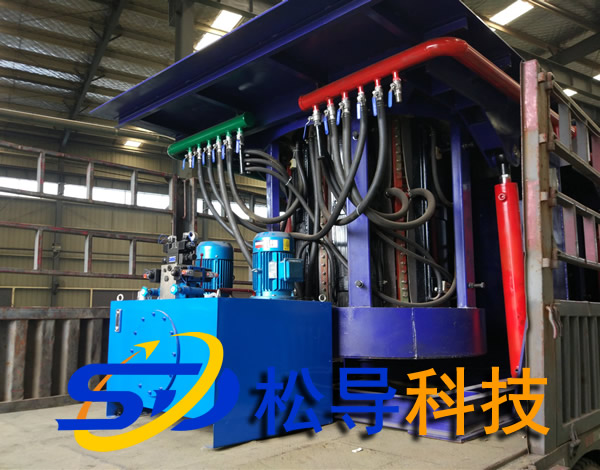
水冷系统是整个炉子装置中的一个重要组成部分,它的安装、调试的正确与否均影响到日后的炉子的正常运行。在安装调试前,首先应检查系统中的各种管道、软管以及相应的接头尺寸是否符合设计要求。进水管最好使用镀锌焊管,如使用普通焊制钢管,则在组装前应对管内壁进行酸洗,清除铁锈和油污。管路中不需拆卸的接头部分可用焊接方法连接,要求焊缝严密,试压时不得有渗漏。管路中的可拆卸部分的接头,其结构应能防止漏水,并便于维修。
水冷系统安装完毕要进行耐水压试验。其方法是水压达到工作压力的最高值,并保持十分钟,所有焊缝及接头处没有渗漏即为合格。然后进行通水和排水的试验,观察感应器、水冷电缆等各冷却水路的流量是否一致,并进行适当的调节,使之符合要求。
备用水源及其切换系统均应在第一次试炉前施工完毕。
-
液压系统的安装和调试
液压驱动装置应具有体积小、灵活轻便和控制操作方便等优点,多数坩埚式中频炉均采用液压倾动系统。油泵站的设计应考虑使用可靠和维修方便,设有多台中频炉的熔化工段,各炉子的液压系统应能相互借用,以减少因维修液压系统而被迫停产的时间。
油泵站一般安装在具有一定高度的基台上,便于维修时从油箱内排油,同时利于安全生产,即使发生严重的漏炉事故也能保证油箱不受铁液的侵袭。在安装输油管道时,也要从最坏的条件出发,任何时候都能避免和高温铁液相遇,防止事故扩大。
消除液压系统中的漏油是一件比较困难的工作,这一点首先从提高安装质量着手。不需拆卸的输油管路的接头,最好采用焊接方法连接。焊缝应致密,不得有渗漏。焊后要清洗其内壁,不得留有焊渣和氧化皮。采用螺纹连接的输油管路接头,在结构上应考虑密封防漏。安装时采用相应的辅助措施,如加防漏涂料等,减少运转过程中产生漏油的可能性。
液压系统安装完毕,应进行整个系统的耐试验。其方法是通入1.5倍工作压力的油,保持15分钟,认真检查每一个接头、焊接及每一个元件的交界面,如有渗漏,应采取措施逐个消除。
炉体、水冷系统、液压系统安装完毕后,应进行炉体倾动试验,对炉子安装质量进行总的检查,如液压控制系统是否灵活可靠,各动作是否正确;炉体、炉盖的运转是否正常;炉体倾转到95°时,限位的行程开关是否起到保险作用,并调节液压系统的压力和流量,使其处于良好的工作状态。倾炉的同时,要检查水冷系统的活动接头的安装质量,不得漏水和妨碍炉体倾转;要检查液压和水冷系统的软管,在炉体倾动时观察长度是否合适,必要时作适当的调整;要检查排水系统在炉体倾斜时是否能正常工作,如发现不足之处,应采取相应措施。
-
电气系统及感应器、磁轭的安装和调试
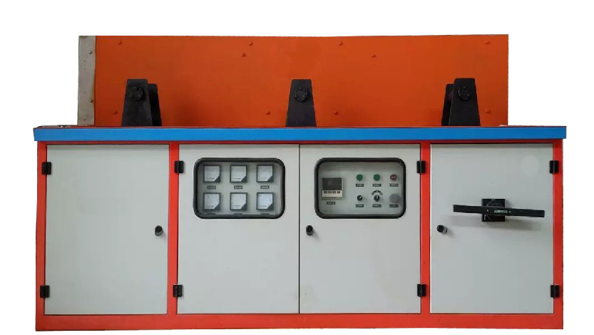
炉子的主电源进线、变压器、电容器、电抗器、各种开关柜和控制柜、主母线、动力线和控制线路的安装,均应参照国家工业企业电气设计安装的有关条例进行,特别要注意的是以下几点:
(1)电气设备间的所有控制线两端均应标出端子号,便于检查和维修。接线完成后要认真反复检查,并试验电气动作,使所有电器及其连锁装置的动作准确无误。
(2)感应器接通水前,要检测感应器的绝缘电阻,并做耐压试验。若感应器已经通水,则需用压缩空气把水吹干后,再进行上述试验。感应器应能承受2Un +1000伏(但不低于2000伏)的绝缘耐压试验1分钟,而无闪络和击穿现象。Un为感应器的额定电压。在高压试验时,电压从1/2Un规定值开始,在10秒钟内增加到最大值。
感应器中感应线圈之间、感应线圈与地之间的绝缘电阻要满足如下要求:额定电压在1000伏以下者,用1000伏摇表,其绝缘电阻值不低于1兆欧;额定电压1000伏以上者,用2500伏摇表,其绝缘电阻值1000欧。如发现绝缘电阻值低于上述值,应对感应器进行干燥处理,可借助于放在炉内的加热器或吹热风进行干燥。但此时应注意防止对绝缘有害的局过热。
(3)磁轭顶紧螺丝是否牢固和拧紧。
炉子在投入运行前必须先确认:所有联锁和信号系统完好,炉体倾转至最大位置时倾限位开关作用可靠,电源、测量仪表和控制保护系统都处于正常状态,然后进行筑炉、打结和烧结炉衬的试验。
How to install and debug the induction melting furnace ?
1. Preparation before installation
Before installation, it is necessary to check whether all the components of the complete set of equipment, the main components of the furnace and the installation materials are complete, and check their condition. The defects of some parts and materials caused by improper transportation and storage should be repaired to ensure that all equipment, parts, corresponding materials and parts are intact to ensure the smooth progress of future installation and commissioning.
In addition, the inspection and acceptance of various civil engineering facilities related to furnace equipment, such as checking whether the main dimensions in the layout are correct; checking whether the foundations, trenches and embedded parts required for the installation of various electrical equipment and main busbars conform to the design Requirements, whether the furnace foundation, platform elevation, deviation of the vertical and horizontal axes, and the position of the anchor screws are within the specified size range; check whether the construction quality of the base and platform meets the requirements. Only after the above preparations are completed, can the furnace be installed and debugged.
2. Installation and commissioning of furnace and electrical equipment
1 . Furnace installation
The installation procedures of the furnace body are specified on the drawings. The first is to install the furnace frame on the flat base, and then install the furnace oil tank and furnace body. If there is a weighing device, it should be installed in the specified position according to the requirements of the drawing. The furnace bracket (for the crucible induction melting furnace includes a fixed bracket and a movable bracket) and the furnace body part, during the processing , the thermal deformation caused by the welding construction should be limited to the specified range of the design . Only in this way can it be ensured Future work proceeded smoothly.
2 . Installation and commissioning of water cooling system
The water-cooling system is an important part of the entire furnace device, and its installation and debugging will affect the normal operation of the furnace in the future. Before installation and commissioning, first check whether the various pipes, hoses and corresponding joint sizes in the system meet the design requirements. It is best to use galvanized welded pipe for the water inlet pipe. If ordinary welded steel pipe is used, the inner wall of the pipe should be pickled before assembling to remove rust and oil stains. The joints in the pipeline that do not need to be disassembled can be connected by welding, and the welding seam is required to be tight, and there should be no leakage during pressure test. The detachable part of the joint in the pipeline should be structured to prevent water leakage and facilitate maintenance.
After the water cooling system is installed, a water pressure test is required. The method is that the water pressure reaches the highest value of the working pressure and keeps it for ten minutes. All welds and joints are qualified if there is no leakage at the joints. Then conduct water and drain tests to observe whether the flow rates of the sensors, water-cooled cables, and other cooling water channels are consistent, and make appropriate adjustments to make them meet the requirements.
The backup water source and its switching system should be completed before the first test furnace.
3 . Installation and commissioning of hydraulic system
The hydraulic drive device should have the advantages of small size, flexibility and lightness, and convenient control and operation. Most crucible induction melting furnace use hydraulic tilting systems. The design of the oil pump station should consider reliable use and convenient maintenance. There are melting sections with multiple induction melting furnaces . The hydraulic systems of each furnace should be able to borrow each other to reduce the time of forced shutdown due to maintenance of the hydraulic system.
The oil pump station is generally installed on a base with a certain height, which is convenient for draining oil from the oil tank during maintenance, and at the same time, it is conducive to safe production. Even if a serious furnace leakage accident occurs, the oil tank can be protected from molten iron. When installing oil pipelines, we must also proceed from the worst conditions, avoid encountering high-temperature iron liquid at any time to prevent the expansion of the accident.
Eliminating the oil leakage in the hydraulic system is a relatively difficult task. This starts with improving the installation quality. The joints of the oil pipeline that do not need to be disassembled should preferably be connected by welding. The weld should be dense and free of leakage. After welding, clean the inner wall without leaving welding slag and oxide scale. For oil pipeline joints with threaded connections, sealing and leak-proofing should be considered in the structure. When installing, adopt corresponding auxiliary measures, such as adding anti-leakage paint, to reduce the possibility of oil leakage during operation.
After the hydraulic system is installed, the endurance test of the entire system should be carried out. The method is to pass in 1.5 times the working pressure of the oil, keep it for 15 minutes, carefully check every joint, welding and the interface of every component, if there is any leakage, measures should be taken to eliminate one by one.
After the furnace body, water cooling system, and hydraulic system are installed, the furnace body tilting test should be carried out, and the overall inspection of the furnace installation quality, such as whether the hydraulic control system is flexible and reliable, whether each action is correct; whether the furnace body and furnace cover are operating normally ; When the furnace body is tilted to 95 °, whether the limit switch plays an insurance role, and adjusts the pressure and flow of the hydraulic system to make it in a good working condition. While tilting the furnace, check the installation quality of the movable joints of the water-cooling system. No water leaks or hinder the tilting of the furnace body; check the hoses of the hydraulic and water-cooling system, observe whether the length is appropriate when the furnace body is tilted, and make appropriate measures if necessary. Adjust; check whether the drainage system can work normally when the furnace body is tilted. If any deficiencies are found, corresponding measures should be taken.
4 . Installation and debugging of electrical systems, inductors, and magnetic yokes
The installation of the main power supply line, transformers, capacitors, reactors, various switch cabinets and control cabinets, main bus bars, power lines and control lines of the furnace should be carried out in accordance with the relevant regulations of the national industrial enterprise electrical design and installation, and special attention should be paid Is the following:
( 1 ) The terminal numbers should be marked on both ends of all control wires in the electrical equipment room to facilitate inspection and maintenance. After the wiring is completed, check repeatedly and test the electrical actions to ensure that the actions of all electrical appliances and their interlocking devices are correct.
( 2 ) Before the sensor is connected to the water, the insulation resistance of the sensor should be tested and the withstand voltage test should be done. If the sensor has been watered, you need to use compressed air to dry the water, and then perform the above test. The inductor should be able to withstand an insulation withstand voltage test of 2U n +1000 volts (but not less than 2000 volts) for 1 minute without flashover and breakdown. Un is the rated voltage of the inductor. During the high voltage test, the voltage starts from the specified value of 1/2U n and increases to the maximum value within 10 seconds.
In the inductor, the insulation resistance between the induction coils and between the induction coil and the ground should meet the following requirements: For those with a rated voltage below 1000 volts, use a 1000 volt shaker, and the insulation resistance value should not be less than 1 megohm; the rated voltage is 1000 For those above volts, use a 2500 volt meter with an insulation resistance of 1000 ohms. If the insulation resistance value is found to be lower than the above value, the inductor should be dried, which can be dried with the help of a heater placed in the furnace or blowing hot air. At this time, however, care should be taken to prevent local overheating that is harmful to the insulation.
( 3 ) Whether the yoke top screw is firm and tightened.
The furnace must be confirmed before it is put into operation: all interlocking and signal systems are intact, the tilt limit switch is reliable when the furnace body is tilted to the maximum position, and the power supply, measuring instruments and control and protection systems are in normal conditions, and then the furnace is built, Tests for knotting and sintering the lining.
手 机:15038554363
