洛阳松导感应加热科技有限公司
联系方式:15038554363
24小时技术热线:15038554363
邮 箱:1390003299@qq.com
厂址:河南省洛阳市洛新工业园区
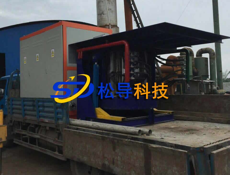
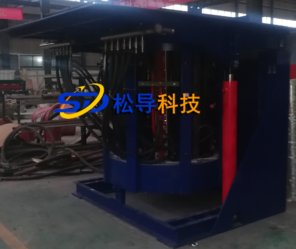
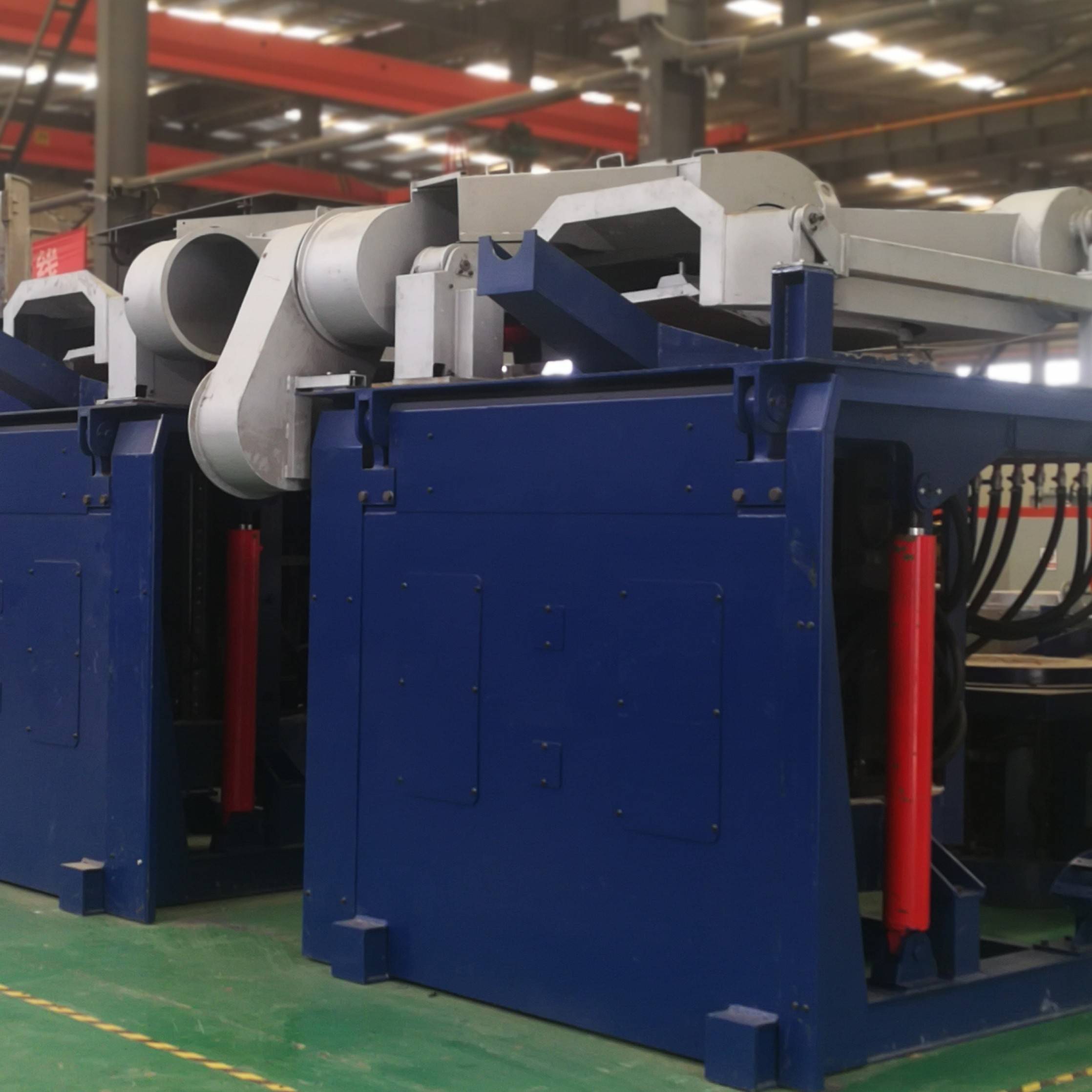
14中频感应熔化炉故障附附维修方法
维修前的准备
1、维修时所需的工具有:万用表、20兆以上双踪示波器、电烙铁、螺丝刀、扳手等。
2、维修时所需要的资料有:设备有关电气图纸、说明书等技术资料。
3、维修前应首先了解设备的故障现象,出现故障时所发生的情况,以及查看设备的记录资料。
4、准备一些易损和常用的元器件。
十四条故障的维修
一、中频感应熔化炉设备无法启动,启动时只有直流电流表有指示,直流电压、中频电压表均无指示。故障分析及处理:这是一种最常见的故障现象,造成的原因可能是:
①、逆变触发脉冲有缺脉冲现象――用示波器检查逆变脉冲(最好在可控硅的AK上检查),如发现有缺脉冲现象,检查连线是否有接触不良或开路,前级是否有脉冲输出。
②、逆变可控硅击穿――更换可控硅,并检查可控硅损坏原因(有关可控硅损坏原因参见后面的可控硅损坏原因分析)。
③、电容器击穿――拆除损坏的电容器极柱。
④、负载有短路、接地现象――排除短路点和接地点。
⑤、中频信号取样回路有开路或短路现象――用示波器观察各信号取样点的波形,或在不通电的情况下用万用表测量各信号取样回路的电阻值,查找开路点或短路点。
二、启动较困难,启动后中频电压高出直流电压的一倍,且直流电流过大。 故障分析及处理:造成这种故障的原因有:
①、逆变回路有一只可控硅损坏――当逆变回路有一只可控硅损坏时,设备有时也可启动,但启动后会出现上述故障现象,更换损坏的可控硅,并检查损坏原因。
②、中频信号取样回路有开路或极性错误现象――这种原因多在采用交角法的线路中,中频电压信号开路或在维修其它故障时将中频电压信号的极性接反,均会造成此故障现象。
③、逆变引前角移向电路出现故障――中频电源的负载是呈容性的,即:电流超前于电压。在取样控制电路中,都设计有移相电路,如果移相电路出现故障也会造成此故障现象
三、启动困难,启动后直流电压最高只能升到400V,且电抗器震动大,声音沉闷。 故障分析及处理:这种故障是三相全控整流桥故障,其主要原因是:
①、整流可控硅开路、击穿、软击穿或电参数性能下降――用示波器观察各整流可控硅的管压降波形,查找损坏的可控硅后更换。当损坏的可控硅击穿时,其管压降波形为一条直线;软击穿时电压升到一定时为一条直线,电参数下降时电压升到一定值时波形发生变化。如果出现上述现象,直流电流就会出现断流现象,造成电抗器震动。
②、缺少一组整流触发脉冲――用示波器分别检查各路触发脉冲(最好在可控硅上检查),检查出没有脉冲的回路时,用倒推法确定故障位置,更换其损坏器件。当出现这种现象时,直流电压的输出波头就会缺少一个波头,造成电流断流,产生此故障现象。
四、能够启动,但启动后又马上停机,设备处于不断重复启动状态。故障分析及处理:这种故障是属于扫频式启动方式的设备故障,其原因是:
①、逆变引前角过小,启动后由于换相失败而引起的重复启动 ――用示波器通过观察中频电压波形,将逆变引前角适当调大。
②、负载振荡频率信号在它激扫描频率信号范围的边缘位置――重新调整它激扫描频率的扫描范围。
五、中频感应熔化炉设备启动后,当功率升到一定值时设备过流保护动作,有时会烧坏可控硅元件,重新启动,现象依然如故。 故障分析及处理:
这种故障现象一般是由于以下两种原因造成:
①、逆变可控硅水冷套内断水或散热效果下降――更换水冷套。有时观察水冷套的出水量和压力是足够的,但经常由于水质问题,在水冷套的壁上附着一层水垢,由于水垢是一种导热性级差的物体,虽然有足够的水流量流过,但因为水垢的隔离是其散热效果大大降低。其判断方法是:将功率运行在较低于该过流值的功率下约十分钟,迅速停机,停机后迅速用手触摸可控硅元件的芯部,若感觉到烫手,则该故障是由此原因引起的。
②、槽路连接导线有接触不良和断线情况――检查槽路连接导线,根据实际情况酌情处理。当槽路连接导线有接触不良或断线情况时,功率升到一定值后会产生打火现象,影响了设备的正常工作,从而导致设备保护动作。有时因打火时会在可控硅两端产生瞬时过电压,如果过压保护动作来不及,会烧坏可控硅元件。该现象经常会出现过电压、过电流同时动作。
六、设备启动时无任何反应,经观察,控制线路板上的缺相指示灯亮。故障分析及处理:
这种故障现象较为明显,是由以下原因引起的:
①、快速熔断器烧断――一般快速熔断器都有熔断指示,可通过观察其指示来判断熔断是否烧断,但有时因快速熔断器使用时间过久或质量原因,不指示或指示不明确,须断电后用万用表测量。处理方法是:更换快速熔断器,分析烧断原因。一般烧断快速熔断器的原因有两种: 设备在长时间大功率、大电流的条件下运行造成快速熔断器发热,使熔芯热熔。 整流控制电路故障造成瞬时大电流冲击波击。应对整流电路进行检查。 整流负载或中频负载短路,造成瞬时大电流冲击,烧坏快速熔断器,检查其负载回路。
②、主令开关的触头烧坏或前级供电系统有缺相故障――用万用表的交流电压档测量每一级的线电压,判断故障位置。
七、设备运行时直流电流以达到额定值,但直流电压和中频电压低,用示波器观察其中频电压波形,波形正常且逆变引前角也正常。故障分析及处理:该故障现象不属于中频电源故障,而是由于负载的阻抗过低引起的,须对负载阻抗重新调整。
①、在升压负载的电路中,由于串连补偿电容器的损坏将其拆除,没有更换,或者一味的最求高功率而无节制的增加补偿电容器,使负载的补偿量过补偿,都会造成此故障现象。解决方法是重新调整补偿电容器的补偿量,使设备能在额定功率下运行。
②、感应器有匝间短路现象――如果感应器有匝间短路现象,其负载的阻抗也会随之降低,造成此故障现象。匝间短路有两种可能: 感应器的铜管直接短路。 感应器的固定胶木柱严重炭化,由于炭具有导电特性,故造成感应器匝间由炭化的胶木使其匝间直接连接造成感应器匝间短路。解决方法是排除匝间短路现象。
八、设备运行时直流电压、中频电压均以达到额定值,但直流电流小,功率低。 故障分析及处理:该故障现象与“8.2.7”故障现象的原因相反,是由于负载阻抗高引起的。
①、负载补偿电容器的补偿量不足――增加补偿电容器。
②、槽路(负载LC振荡回路)连接导线的节点接触电阻过大――由于设备长时间的使用,其槽路铜排的连接处受灰尘的影响,使其接触电阻增大,造成负载的阻抗增高,出现此故障现象。
九、设备运行正常,直流电流指示偏高,如果将电流庙宇在额定值,则电压太低,且功率表的指示值与直流电压直流电流和乘积不符,而以前是相符的。 故障分析及处理:
这种故障现象有些类似于“七”的故障现象,但有所区别。故障的原因是因为直流电流表的指示不准确,而给人造成一种错觉,误以为电流大。 这种故障的原因较为隐蔽,一时很难发现。如果仔细分析,便可发现,功率的指示值与电压、电流的乘积不符,说明仪表的显示值可能有误。电压值可采用万用表的直流电压档去进行校对,电流值我们可通过用钳形电流表测量进线电流,然后乘以0.816的办法来校对。如果不符,则说明电流表指示不准确。 直流电流表的值是取自分流器上产生的75mV电压信号,在使用时间较长、使用环境较恶劣的条件下,分流器上的接线与分流器之间存在污垢或氧化现象,接触电阻增大,使分流器上产生的电压增高,大于75mV,致使直流电流表的指示偏大。 处理方法是:处理分流器与其接线间的污垢和氧化层。
十、中频感应熔化炉设备运行正常,但停机后启动无任何反应,也无任何保护指示。故障分析及处理:这类故障有两种可能:
①、中频启动开关坏――中频启动开关在中频停止位置时处于接地状态(接在开关的闭点),如果开关坏,则无法打开接地状态,设备处于保护状态,故启动无反应。处理方法:更换中频启动开关。
②、保护电路故障――如参考“控制电路原理图“中,集成电路IC4在运行过程中发热就会导致这一故障。处理方法:给IC4集成电路散热或加散热器。 ③、给定电路中,给定信号中断――在给定电路中,信号给定过程中某处开路,致使无法对整流脉冲进行移相,也会造成此故障现象。处理方法:采用倒推法对给定电路进行检查。
十一、频繁烧坏可控硅元件,更换新可控硅后,马上烧坏。故障分析及处理:这是一种让人比较头疼,维修比较困难的故障现象。可控硅的价格比较昂贵,而烧坏可控硅却让人防不胜防,所以在维修这类故障时要格外小心谨慎。我们在分析故障“2.5“时,介绍了一种烧坏可控硅的原因。除此之外,还有以下原因:
①、可控硅在反相关断时,承受反向电压的瞬时毛刺电压过高――在中频电源的主电路中,瞬时反相毛刺电压是靠阻容吸收来吸收的。如果吸收电路中电阻、电容开路均会使瞬时反相毛刺电压过高烧坏可控硅。在断电的情况下用万秀表测量吸收电阻阻值、吸收电容容量,判断是否阻容吸收回路出现故障。
②、负载对地绝缘降低――负载回路的绝缘降低,引起负载对地间打火,干扰了脉冲的触发时间或在可控硅两端形成高压,烧坏可控硅元件。
③、脉冲触发回路故障――在设备运行时如果突然丢失触发脉冲,将造成逆变开路,中频电源输出端产生高压,烧坏可控硅元件。这种故障一般是逆变脉冲形成、输出电路故障,可用示波器进行检查,也可能是逆变脉冲引线接触不良,可用手摇晃导线接头,找出故障位置。
④、设备在运行时负载开路――当设备正在大功率运行时,如果突然负载处于开路状态,将在输出端形成高压烧坏可控硅元件。
⑤、设备在运行时负载短路――当设备在大功率运行时,如果负载突然处于短路状态,将对可控硅有一个很大的短路电流冲击,若过电流保护动作不不及保护,将烧坏可控硅元件。
⑥、保护系统故障(保护失灵)――可控硅能否安全,主要是告保护系统来保证的,如果保护系统出现故障,设备稍有一点工作不正常,将危机到可控硅安全。所以,当可控硅烧坏时对保护系统的检查是必不可少的。
⑦、可控硅冷却系统故障――可控硅在工作时发热量很大,需要对其冷却才能保证正常工作,一般可控硅的冷却有两种方式:一种是水冷,另一种是风冷。水冷的应用较为广泛,风冷一般只用于100KW以下的电源设备。通常采用水冷方式的中频设备均设有水压保护电路,但基本上都是总进水的保护,若某一路出现水堵,是无法保护的。
⑧、电抗器故障――电抗器内部打火造成逆变侧的电流断续,也会在逆变输入侧产生高压烧坏可控硅。另外,如果在维修中更换了电抗器,而电抗器的电感量、铁芯面积小于要求值,会使电抗器在大电流工作时,因饱和失去限流作用烧坏可控硅。
十二、启动设备时,当打开中频启动开关,主电路开关保护跳闸或过电流保护。 故障分析及处理:
①、功率调节旋钮在最高位置――除淬火负载,其它载要求设备在启动时将功率调节旋钮放在最小位置,如果不再最小位置,就会因电流冲击太大而过电流保护或主电路开关保护跳闸。
②、电流调节器故障――当电流调节器电路故障,尤其是电流互感器损坏或接线开路时,启动无电流反馈抑制,直流电压就会直接冲击到最大(Q角20度),直流电流会直接冲击到最大值,造成过电流保护或主电路开关跳闸。处理方法:检查电流互感器是否损坏;电流互感器至电路板的接线是否断线情况;电流调节器部分是否有元器件损坏、开路现象。
十三、中频变压器烧坏,更换后启动设备依旧烧坏中频变压器。 故障分析及处理:
这种故障常见于在采用升压负载的设备上,主要是因为泄放电感开路引起的。在升压负载中,串连电容器组和并联电容器组两端的电压不可能绝对一致,在两组补偿电容器放电时,由于端电压不一致,其放电时间的长短也不一样,则电压高的放电时间慢,而这组电容器还没有完全放电完成时又开始充电过程,在此电容器组上就会积累直流电荷,这些直流电荷要通过泄放电感进行释放,如果泄放电感开路,电容器上积累的直流电荷就会通过中频变压器释放,由于中频变压器的容量很小,承受不了这么大的电流流过,引起中频变压器烧坏。
十四、在升压负载中泄放电感发热甚至烧坏。 故障分析及处理:引起泄放电感发热的原因有以下三点:
①、在上例故障分析中,如果串并联组电容器的容量差别很大,会造成直流电荷释放的电流增大,若泄放电感的容量较小就会引起发热。
②、逆变脉冲不对称――逆变器对逆变脉冲的要求是两组脉冲互差 180°,如果逆变脉冲差不是180°,则逆变输出电压的正负半周的时间也不一致,导致补偿电容器在一个周期两次充电的时间不一致,那么时间长的半周给电容器充的电还未放完时,时间短的半周以开始给电容器充电,在电容器上就积累了一定电荷。逆变电压正负半周的时间差别越大,直流电荷就越高,流过泄放电感的电流就越大,当电流达到一定程度时,泄放电感就会引起发热现象甚至烧毁。所以,当泄放电感发热时,一定要仔细检查逆变脉冲的对称度,如果不对称就应分析原因,检查逆变脉冲形成电路,解决逆变脉冲不对称现象。在逆变脉冲形成电路中,两路脉冲形成电路是对称的。如果出现逆变脉冲不对称,一般可能是由于电容器容量、电阻阻值变化引起,也能是集成电路内部参数变化引起。
③、逆变可控硅有一只烧坏――当一只逆变可控硅烧坏后,设备常常可以启动这时如果不注意观察设备的运行状态,让设备带病工作,中频输出电压波形是畸变的波形。通过上面的分析,我们可以看出,泄放电感流过的电流很大,引起泄放电感发热或烧坏。 3、维修技巧 在设备维修时我们经常可以发现在维修时花费了大量的经历和时间,往往在最后的原因很简单如:连线虚接、螺丝未紧固、断水、某器件烧坏等原因。为了缩短维修时间,就需要我们在维修时不断的总结经验,勤于观察,同时也要掌握一些维修技巧。 和医生给病人看病一样,在中频电源维修时需要望、闻、问、切后判断故障位置。 望:所谓望就是观察设备在运行时其仪表的参数、设备内有无发热、发红、锣丝松动等外观现象,这里我们主要介绍有关仪表参数和设备运行状态的关系。在中频电源运行时中频电压、直流电压、直流电流三个仪表之间有着密切的联系,我们通过观察这三个仪表的参数即可判断出中频电源是否运行正常。我们知道,直流电压和直流电流的乘积是直流功率,直流电压和直流电流的比值可以反映出负载的阻抗匹配状态。如:250KW的中频设备,直流电压的最高平均值是513V,直流电流的最高平均值是500A,如果设备在运行时直流电压达到500V,而直流电流值为500A,那么其阻抗达到了最佳匹配值。若直流电流小于500A,其阻抗值偏高,若直流电流大于500A,则阻抗值偏低。这就是说:我们可以通过观察直流电流和直流电压的值可以看出负载阻抗的匹配状况。 直流电压和中频电压的比例可反映出逆变器的工作状态,例如:直流电压为510V,中频电压为700V,逆变的引前角就为36°,我们用700V÷510V=1.37。一般,中频电压和直流电压的比例在1.2~1.5之间我们均认为逆变器工作正常.如果比例小于1.2,则引前角太小,逆变器很难换相;如果大与1.5倍,则引前角太大,有可能设备有故障;如果大于两倍,则设备有故障。 闻:所谓闻是指设备在运行时听其声,一听中频啸叫声中有无杂声、声音是否连续、有无沉闷有电抗器振动声;二是听有无打火声音等与平时声音不同之处。 问:所谓问是指了解设备在出现故障时的状况,了解时要尽量详细,同时也要了解在设备出故障前的运行状况。
Fourteen medium frequency induction melting furnace fault attached maintenance method
Preparation before maintenance
1, the tools required for maintenance are: multimeter, 20 megabytes or more double trace oscilloscope, electric iron, screwdriver, wrench and so on.
2, the information required for maintenance are: equipment related to electrical drawings, instructions and other technical information.
3. Before repairing, you should first understand the fault phenomenon of the equipment, what happened when the fault occurred, and check the records of the equipment.
4. Prepare some vulnerable and commonly used components.
Fourteen fault repairs
1. The medium frequency induction melting furnace equipment cannot be started. Only the DC current meter has an indication when starting, and there is no indication of the DC voltage and the intermediate frequency voltmeter. Fault Analysis and Processing: This is one of the most common failure phenomena, which may be caused by:
1. Inverter trigger pulse has pulse phenomenon - check the inverter pulse with oscilloscope (preferably check on the thyristor AK). If there is a missing pulse, check if the connection has poor contact or open circuit. Is there a pulse output?
2, inverter thyristor breakdown - replace the thyristor, and check the cause of thyristor damage (for the cause of thyristor damage, see the analysis of the cause of thyristor damage).
3. Capacitor breakdown - remove the damaged capacitor pole.
4, the load has a short circuit, grounding phenomenon - eliminate the short circuit point and grounding point.
5. The IF signal sampling loop has open circuit or short circuit phenomenon―use the oscilloscope to observe the waveform of each signal sampling point, or use a multimeter to measure the resistance value of each signal sampling loop when the power is not supplied, and find the open circuit point or short circuit point.
Second, the startup is more difficult. After starting, the intermediate frequency voltage is twice as high as the DC voltage, and the DC current is too large. Fault Analysis and Handling: The causes of this failure are:
1. The inverter circuit has a thyristor damage. When the inverter circuit has a thyristor damaged, the device can sometimes be started, but the above failure phenomenon will occur after startup, replace the damaged thyristor, and check for damage. the reason.
2. The intermediate frequency signal sampling loop has an open circuit or a polarity error phenomenon. This is mostly caused by the intersection angle method. When the intermediate frequency voltage signal is open or the polarity of the intermediate frequency voltage signal is reversed during maintenance of other faults, it will cause This malfunction phenomenon.
3, the inverter leads to the front angle shifting circuit failure - the load of the intermediate frequency power supply is capacitive, that is: the current leads the voltage. In the sampling control circuit, a phase shifting circuit is designed, which may be caused if the phase shifting circuit fails.
Third, the difficulty of starting, after the start up, the DC voltage can only rise to 400V, and the reactor vibration is large, the sound is dull. Fault analysis and processing: This fault is a three-phase full-controlled rectifier bridge fault, the main reasons are:
1. Rectifier thyristor open circuit, breakdown, soft breakdown or electrical parameter performance degradation - Observe the tube voltage drop waveform of each rectifier thyristor with an oscilloscope, and find the damaged thyristor after replacement. When the damaged thyristor breaks down, the tube voltage drop waveform is a straight line; when the voltage is softened, the voltage rises to a certain line, and the waveform changes when the voltage rises to a certain value when the electrical parameter drops. If the above phenomenon occurs, the DC current will be interrupted, causing the reactor to vibrate.
2, the lack of a set of rectification trigger pulse - use the oscilloscope to check each trigger pulse (preferably on the thyristor), check the loop without a pulse, use the back push method to determine the fault location, replace the damaged device. When this phenomenon occurs, the output wave head of the DC voltage lacks a wave head, causing current interruption, which causes this malfunction.
Fourth, it can be started, but it will stop immediately after starting, and the equipment is constantly restarting. Fault analysis and processing: This fault is a device fault that belongs to the sweeping start mode. The reason is:
1. The front angle of the inverter is too small, and the restart is caused by the failure of the commutation after starting up. By using the oscilloscope to observe the intermediate frequency voltage waveform, the front angle of the inverter is appropriately adjusted.
2. The load oscillating frequency signal is at the edge of its excitation sweep frequency signal range - re-adjusting the scan range of its excitation sweep frequency.
5. After the medium frequency induction melting furnace equipment is started, when the power rises to a certain value, the equipment overcurrent protection action will sometimes burn out the thyristor components and restart, the phenomenon remains the same. Fault analysis and processing:
This type of failure is generally caused by two reasons:
1. Inverter thyristor water-cooled jacket has a reduced water or heat dissipation effect - replace the water-cooled jacket. Sometimes it is sufficient to observe the water output and pressure of the water jacket, but often due to water quality problems, a layer of scale is attached to the wall of the water jacket. Since the scale is an object with poor thermal conductivity, although there is enough water flow, However, because the scale is isolated, its heat dissipation effect is greatly reduced. The method of judging is: running the power at a power lower than the overcurrent value for about ten minutes, quickly stopping the machine, and quickly touching the core of the thyristor element by hand after stopping, if the hand feels hot, the fault is caused by Caused by this.
2. Poor contact and disconnection of the connecting line of the tank road - check the connecting line of the tank, and handle it according to the actual situation. When the connection line of the tank circuit has poor contact or disconnection, the fire will rise after a certain value rises, which will affect the normal operation of the equipment and cause the equipment to protect. Sometimes a transient overvoltage occurs across the thyristor due to a fire. If the overvoltage protection action is too late, the thyristor component will burn out. This phenomenon often occurs when overvoltage and overcurrent occur simultaneously.
6. There is no reaction when the equipment starts. After observation, the phase loss indicator on the control circuit board is on. Fault analysis and processing:
This kind of failure phenomenon is more obvious and is caused by the following reasons:
1. Fast-blow fuse--General fast-blow fuses have blown indications. You can observe whether the fuses are blown by observing the indications, but sometimes the fast-acting fuses are used for too long or quality reasons, and the indications are not indicated or the indications are not clear. It must be measured with a multimeter after power off. The treatment method is: replace the fast fuse and analyze the cause of the blow. There are two reasons for the blown fuses: The equipment runs under the conditions of long time, high power and high current, which causes the fuses to heat up and fuse the fuses. The rectifier control circuit fault causes an instantaneous large current shock wave strike. The rectifier circuit should be checked. The rectified load or the intermediate frequency load is short-circuited, causing an instantaneous large current surge, burning the fast fuse and checking its load circuit.
2. The contact of the main switch is burned out or the front-end power supply system has a phase loss fault. Use the multimeter's AC voltage file to measure the line voltage of each stage to determine the fault location.
7. When the equipment is running, the DC current reaches the rated value, but the DC voltage and the intermediate frequency voltage are low. The waveform of the intermediate frequency is observed with an oscilloscope. The waveform is normal and the front angle of the inverter is normal. Fault analysis and processing: The fault phenomenon does not belong to the intermediate frequency power supply fault, but is caused by the low impedance of the load, and the load impedance must be readjusted.
1. In the circuit of boost load, it is removed due to the damage of the series compensation capacitor, and there is no replacement, or the most demanding high-power and uncontrolled increase of the compensation capacitor, so that the compensation amount of the load is over compensated, this will cause this. Failure phenomenon. The solution is to readjust the compensation amount of the compensation capacitor so that the device can operate at rated power.
2. The sensor has a short circuit between the turns - if the sensor has a short circuit between the turns, the impedance of the load will also decrease, causing this malfunction. There are two possibilities for short-circuit between turns: The copper tube of the sensor is directly short-circuited. The fixed bakelite column of the sensor is severely carbonized. Due to the conductive property of the carbon, the carbonized bakelite between the inductors causes the direct connection between the turns to cause short circuit between the turns of the inductor. The solution is to eliminate the short circuit between turns.
8. When the equipment is running, the DC voltage and the intermediate frequency voltage are all up to the rated value, but the DC current is small and the power is low. Fault Analysis and Processing: This fault phenomenon is contrary to the cause of the "8.2.7" fault phenomenon due to the high load impedance.
1. The compensation amount of the load compensation capacitor is insufficient - increase the compensation capacitor.
2. The contact resistance of the connecting line of the tank circuit (load LC oscillation circuit) is too large. Due to the long-term use of the equipment, the connection of the copper strip of the tank is affected by dust, which increases the contact resistance and causes the load. The impedance increases and this failure occurs.
Nine, the equipment is operating normally, the DC current indication is too high. If the current temple is at the rated value, the voltage is too low, and the indication value of the power meter does not match the DC voltage DC current and the product, which was consistent with the previous one. Fault analysis and processing:
This kind of fault phenomenon is somewhat similar to the "seven" fault phenomenon, but it is different. The cause of the fault is because the indication of the DC ammeter is inaccurate, and it creates an illusion that the current is large. The cause of this failure is more subtle and difficult to find. If you analyze it carefully, you can find that the indicated value of power does not match the product of voltage and current, indicating that the displayed value of the meter may be incorrect. The voltage value can be checked by the multimeter's DC voltage file. The current value can be corrected by measuring the incoming current with a clamp ammeter and multiplying by 0.816. If it does not match, the ammeter indication is not accurate. The value of the DC ammeter is taken from the 75mV voltage signal generated by the shunt. Under the condition of long service life and harsh operating environment, there is dirt or oxidation between the wiring and the shunt on the shunt, and the contact resistance increases. , the voltage generated on the shunt is increased, greater than 75mV, causing the indication of the DC ammeter to be too large. The treatment is to treat the dirt and oxide layer between the shunt and its wiring.
10. The medium frequency induction melting furnace equipment is operating normally, but there is no reaction after starting the machine, and there is no protection indication. Fault analysis and processing: There are two possibilities for this type of fault:
1. The IF start switch is broken. The IF start switch is grounded at the intermediate frequency stop position (connected to the closed point of the switch). If the switch is broken, the ground state cannot be turned on and the device is in the protection state, so there is no response. Solution: Replace the IF start switch.
2, protection circuit failure - such as the reference "control circuit schematic", integrated circuit IC4 heat during operation will cause this failure. Processing method: heat the IC4 integrated circuit or add a heat sink. 3. In a given circuit, a given signal is interrupted―in a given circuit, an open circuit somewhere during the signal given process, which makes it impossible to phase shift the rectified pulse, which also causes this malfunction. Treatment method: The reverse circuit is used to check the given circuit.
11. Frequent burnout of the thyristor components. Immediately after replacing the new thyristor, it will burn out. Fault analysis and processing: This is a fault phenomenon that makes people more troublesome and difficult to repair. SCRs are expensive, and burnt thyristors are hard to guard against, so be careful when repairing such faults. When we analyzed the fault "2.5", we introduced a reason for burning the thyristor. In addition to this, there are the following reasons:
1. When the thyristor is in anti-correlation, the instantaneous glitch voltage withstand reverse voltage is too high - in the main circuit of the intermediate frequency power supply, the instantaneous reverse glitch voltage is absorbed by the RC absorption. If the resistors and capacitors in the snubber circuit are open, the instantaneous reverse glitch voltage will be too high to burn out the thyristor. In the case of power failure, use the Wanxiu meter to measure the resistance of the absorption resistor and the capacity of the absorption capacitor to determine whether the resistance-capacitance absorption circuit has failed.
2. Load-to-ground insulation is reduced - the insulation of the load circuit is reduced, causing the load to ignite between the ground, disturbing the triggering time of the pulse or forming a high voltage across the thyristor, and burning the thyristor component.
3, pulse trigger loop fault - if the trigger pulse is suddenly lost when the device is running, it will cause the inverter to open, the high voltage output of the intermediate frequency power supply generates high voltage, and the thyristor component is burned out. This type of fault is generally caused by inverter pulse formation and output circuit failure. It can be inspected by an oscilloscope. It may also be that the inverter pulse lead is in poor contact. You can shake the wire connector by hand to find the fault location.
4. The device is open when the device is running. When the device is running at high power, if the load is suddenly open, a high voltage burnout thyristor component will be formed at the output.
5. The device is short-circuited during operation. When the device is running at high power, if the load is suddenly in a short-circuit state, it will have a large short-circuit current impact on the thyristor. If the over-current protection action is not in protection, it will burn. Bad thyristor components.
6, protection system failure (protection failure) - thyristor can be safe, mainly to protect the system to ensure that if the protection system fails, the equipment is a little bit work is not normal, the crisis will be thyristor safety. Therefore, inspection of the protection system is essential when the thyristor is burned out.
7. Thyristor cooling system failure - The thyristor generates a lot of heat during operation, and it needs to be cooled to ensure normal operation. Generally, there are two ways to cool the thyristor: one is water cooling, the other is The air is cold. Water cooling is widely used, and air cooling is generally only used for power equipment below 100KW. Water-cooled medium-frequency equipment is usually equipped with a water pressure protection circuit, but it is basically the protection of the total influent. If a water block is blocked, it cannot be protected.
8. Reactor failure - The internal ignition of the reactor causes the current on the inverter side to be interrupted, and a high voltage burnout thyristor is also generated on the inverter input side. In addition, if the reactor is replaced during maintenance, and the inductance and core area of the reactor are less than the required value, the reactor will burn out the thyristor due to saturation loss of current limit during high current operation.
12. When the device is started, when the IF start switch is turned on, the main circuit switch protects trip or overcurrent protection. Fault analysis and processing:
1. The power adjustment knob is at the highest position - except for the quenching load, the other equipment requires the power adjustment knob to be placed at the minimum position at startup. If the position is no longer the minimum position, the current surge is too large and the overcurrent protection or main circuit The switch protects from tripping.
2, current regulator failure - when the current regulator circuit failure, especially when the current transformer is damaged or the wiring is open, start the no-current feedback suppression, the DC voltage will directly hit the maximum (Q angle 20 degrees), DC current will Direct impact to the maximum, causing overcurrent protection or main circuit switch trip. Treatment method: Check whether the current transformer is damaged; whether the current transformer to the circuit board is disconnected; whether the current regulator part has component damage or open circuit.
13. The intermediate frequency transformer is burnt out. After the replacement, the starting equipment still burns out the intermediate frequency transformer. Fault analysis and processing:
This type of fault is common on equipment that uses a boost load, mainly because of the open drain. In the boost load, the voltage across the series capacitor bank and the shunt capacitor bank cannot be absolutely identical. When the two sets of compensation capacitors are discharged, the discharge time is different because the terminal voltage is inconsistent, and the discharge time is high. Slow, and this group of capacitors has not completed the charging process again, and the charging process is started. The DC charge is accumulated on the capacitor bank. These DC charges are released by the discharge feeling. If the discharge is open, the DC current accumulated on the capacitor The load will be released by the intermediate frequency transformer. Because the capacity of the intermediate frequency transformer is very small, it cannot withstand such a large current flow, causing the intermediate frequency transformer to burn out.
14. In the boosting load, the venting discharge is heated or even burned out. Fault analysis and treatment: There are three reasons for causing venting and venting fever:
1. In the above example failure analysis, if the capacity of the series-parallel group capacitors is very different, the current of the DC charge release will increase, and if the capacity of the discharge and discharge is small, heat will be generated.
2, the inverter pulse is asymmetrical - the inverter's requirement for the inverter pulse is the difference between the two groups of pulses 180°, if the inverter pulse difference is not 180°, the positive and negative half cycles of the inverter output voltage are also inconsistent, resulting in inconsistent compensation capacitors charging twice in one cycle, then the capacitors are charged for half a week. When not finished, the capacitor is charged at a short half-cycle to accumulate a certain amount of charge on the capacitor. The greater the time difference between the positive and negative half cycles of the inverter voltage, the higher the DC charge, and the greater the current flowing through the discharge and discharge. When the current reaches a certain level, the discharge feeling will cause heat or even burn. Therefore, when the venting and discharging sensation is hot, the symmetry of the inverter pulse must be carefully checked. If the asymmetry is concerned, the cause should be analyzed, and the inverter pulse forming circuit should be checked to solve the asymmetry phenomenon of the inverter pulse. In the inverter pulse forming circuit, the two pulse forming circuits are symmetrical. If there is an asymmetry of the inverter pulse, it may be caused by a change in the capacity of the capacitor or the resistance of the resistor, or it may be caused by a change in the internal parameters of the integrated circuit.
3, the inverter thyristor has a burnout - when an inverter thyristor burns out, the equipment can often start. If you do not pay attention to observe the operating state of the equipment, let the equipment work with disease, the intermediate frequency output voltage waveform Is a distorted waveform. Through the above analysis, we can see that the current flowing through the discharge and discharge is very large, causing the venting and discharging feeling to be hot or burnt. 3, maintenance skills In the equipment maintenance, we can often find a lot of experience and time in the maintenance, often in the final reason is very simple: connection virtual connection, screw is not tightened, water, a device burned and other reasons . In order to shorten the repair time, we need to constantly sum up experience during maintenance, diligent observation, but also have some maintenance skills. As with the doctor to see the patient, in the maintenance of the intermediate frequency power supply, you need to look, smell, ask, and cut the fault location. Hope: The so-called hope is to observe the appearance of the instrument's parameters during the operation, whether there is heat, redness, looseness, etc. in the equipment. Here we mainly introduce the relationship between the instrument parameters and the operating state of the equipment. During the operation of the intermediate frequency power supply, there is a close relationship between the three frequency meters, DC voltage and DC current. We can judge whether the intermediate frequency power supply is running normally by observing the parameters of these three meters. We know that the product of DC voltage and DC current is DC power, and the ratio of DC voltage to DC current can reflect the impedance matching state of the load. For example, for 250KW intermediate frequency equipment, the highest average DC voltage is 513V, and the highest average DC current is 500A. If the DC voltage reaches 500V during operation, and the DC current value is 500A, the impedance is the best match. value. If the DC current is less than 500A, the impedance value is high. If the DC current is greater than 500A, the impedance value is low. That is to say: we can see the matching of the load impedance by observing the values of DC current and DC voltage. The ratio of DC voltage to intermediate frequency voltage can reflect the operating state of the inverter. For example, the DC voltage is 510V, the intermediate frequency voltage is 700V, and the lead angle of the inverter is 36°. We use 700V÷510V=1.37. Generally, the ratio of intermediate frequency voltage to DC voltage is between 1.2 and 1.5. We all think that the inverter works normally. If the ratio is less than 1.2, the lead angle is too small, and the inverter is difficult to change phase; if it is 1.5 times larger, then If the lead angle is too large, the device may be faulty; if it is more than twice, the device is faulty.Smell: The so-called smell means that the device listens to its sound while it is running. When it is heard, there is no noise in the middle whistle, whether the sound is continuous, whether there is dull or no vibration of the reactor; the second is to listen to the sound of the fire, etc. The sound is different. Q: The so-called question refers to understanding the condition of the device in the event of a fault. It should be as detailed as possible, and also understand the operating conditions before the device fails.


手 机:15038554363