洛阳松导感应加热科技有限公司
联系方式:15038554363
24小时技术热线:15038554363
邮 箱:1390003299@qq.com
厂址:河南省洛阳市洛新工业园区
一、 烧结炉组成
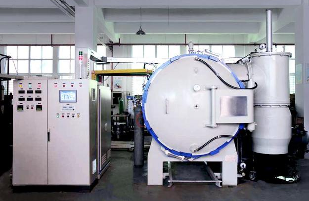
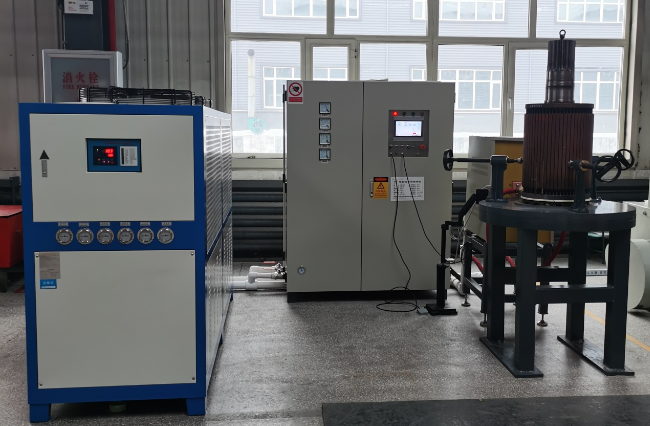
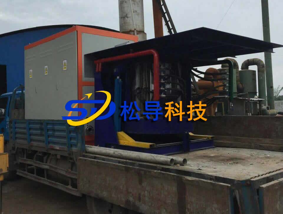
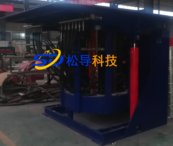
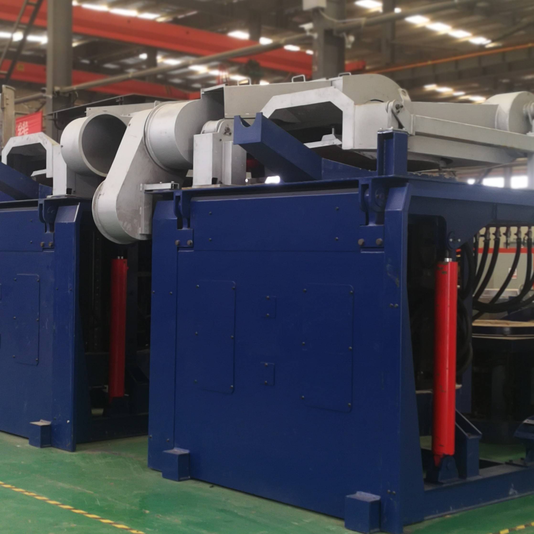
本烧结炉工作方式为下装料间歇作业。烧结炉主要由可控硅中频电源、氢气烧结炉(罐体、耐火材料、钼坩埚等)和温度自动控制系统等组成。
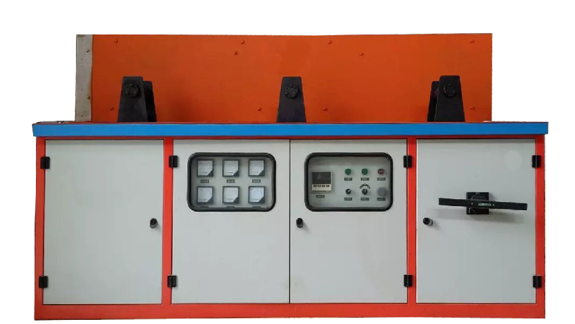
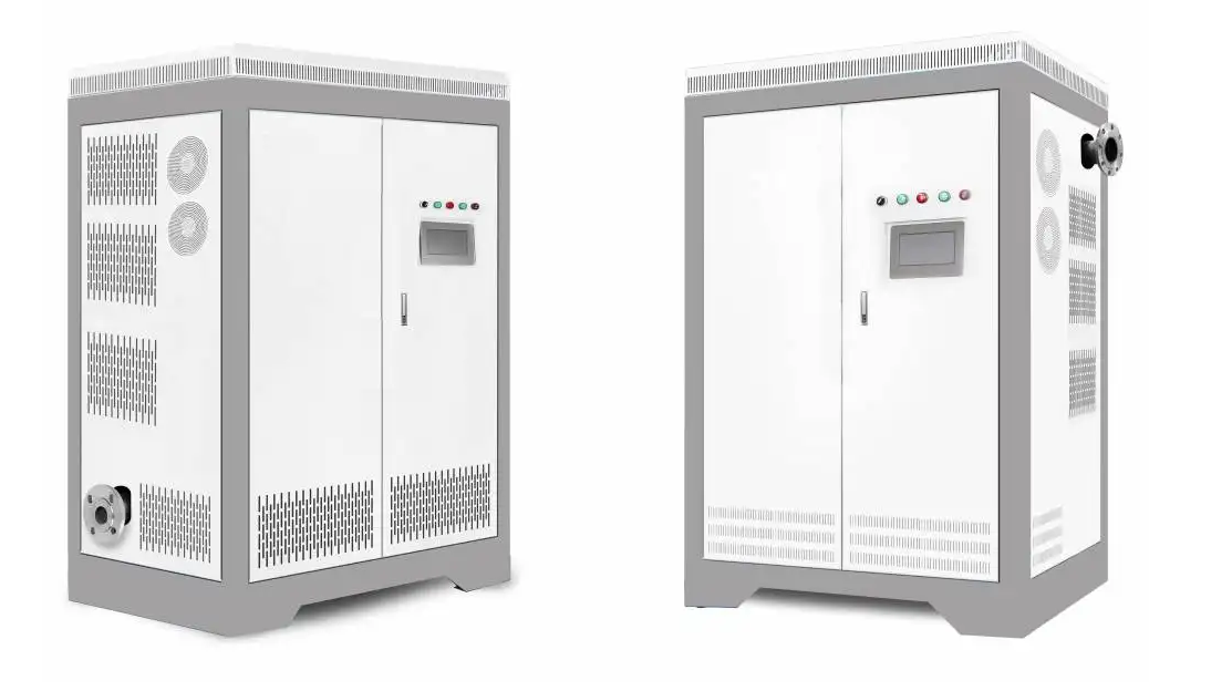
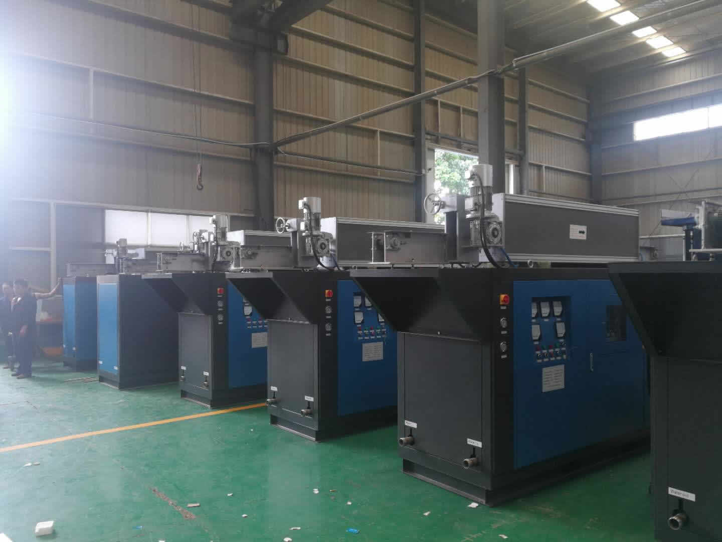
1、可控硅中频电源由KGPS-250/2.5 250KW 2.5KHz电源柜,电热电容器柜,连接铜排,引擎机构组成;
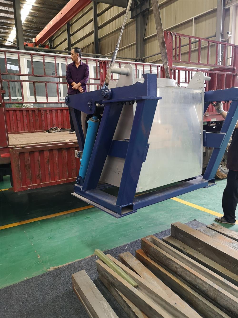
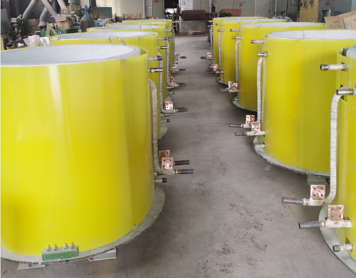
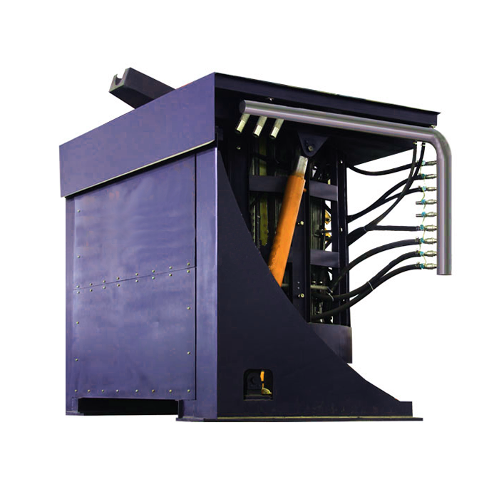
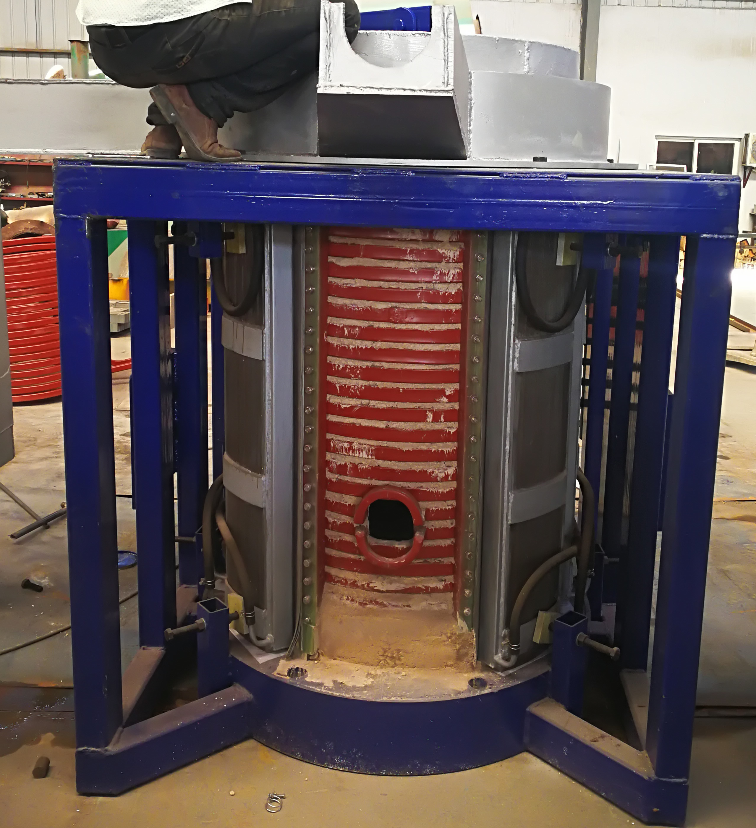
2、烧结炉由罐体、感应器、氧化铝、氧化锆耐火材料、钨坩锅、开启式回水箱、氢气/氮气流量调节阀控制板、台架、下装料机构和移出轨道等组成;
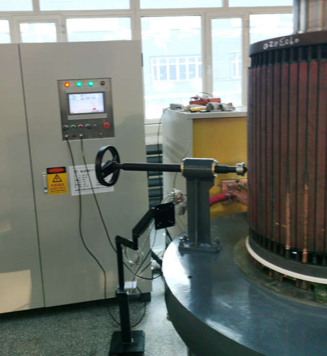
3.温度自动控制系统由Wre5-26热电耦和光纤传感仪测温,由温度调节仪进行控制,由无纸记录仪进行加热温度的记录。整个控制系统安装在一台立式操作台柜上进行控制。
二 、主要技术指标
1、 内坩埚尺寸:φ380(内径)×600
2、 内坩埚材料:烧结钨或喷涂钨
3、 烧结最高温度:2300℃
4、 控温精度:±10℃
5、 外壳工作温升:小于50℃
6、 工作频率:2500Hz
7、 温度自动测量、控制、显示、自动记录和储存。
8、 炉内氢气保护、流量可调、出口设排渣。
9、 氢气耗量:2立方米/小时
10、 具有过流、过压、缺相、水压不足、超温、掉电保护功能
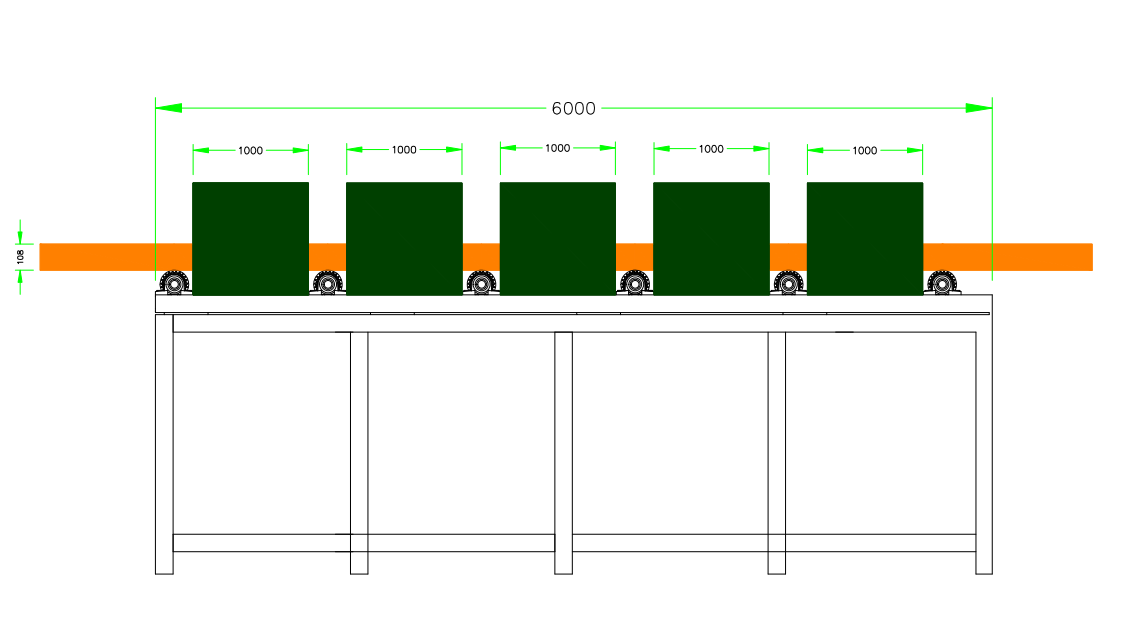
11、 进出料机构上下运行平稳,在装入1000mm高的工件时最高点的摆动不大于5mm.
12、 烧结炉的升降的最大速度为15mm/秒,装料平台平移出速度最大为45mm/秒.
13、 烧结炉数量 1台
三、烧结炉的工作过程:
将工件放置在托盘上,减速电机通过螺杆带动托盘沿移出导轨移动到罐体的下部中心位置,通过定位销连接托盘与升降机构,然后制动电机启动,通过齿轮蜗轮减速机和转向箱带动两根丝杠,将托盘向上升起,到达罐体锥形口与罐体进行连接;连接完成后进行充氢气和鸣爆试验工作。加热完成后工件退出罐体的步骤与上升相反,电机带动托盘向下移动,托盘到底以后脱开与升降机构的连接,横向电机带动托盘沿导轨移出,整个工作完成
四、升降和移出机构:
 升降和移出机构使用机械升降机构,
4.1机械型升降和移出机构:
此机构由四根支撑立柱、四根导柱及导套、齿轮蜗轮减速机,丝杠、转向箱、制动电机、托料盘、工作平台等组成。
4.1.1升降机构中安装有托料盘,制动电机通过齿轮蜗杆减速机带动两根丝杠转动,通过丝杠上的导套与托盘连接,使托盘上下移动,达到上下料的作用。
4.1.2为使托盘在与罐体的连接过程中减少撞击,设计中加入弹簧缓冲结构及限位开关和变频调速机构;
4.1.3 为保证托盘上升下降的过程平稳进行,在机构中设计有四根导柱和导套,通过四个方向的导柱支撑,使托盘能够更加平稳的上升下降;
4.1.4当托盘降到地面后,人工将托盘与升降机构上的连接销拔出,托盘落到移出平台上,此时托盘利用水平安装在地面上的导轨,在电机的控制下拉出和推入进行装卸料;
4.1.5托盘的移出采用电机带动丝杠在导轨上平稳移动,在导轨上安装有限位开关,可控制托盘的移动位置;
4.1.6进出料系统采用变频调速。
4.1.7托盘下部法兰上装有硅橡胶密封圈,当托盘上升到最上端时,通过硅橡胶密封圈进行密封。此时将自锁螺栓紧固,防止升温时漏气,并能防止在高温时由于误动作使托盘法兰打开。
4.1.8托盘上放置氧化锆和刚玉耐火砖,耐火砖和托盘上板留有气路通道,可有效地排出空气。
4.1.9托盘上放置的氧化锆和刚玉耐火砖交错放置,以防止炉内的高温直接辐射到托盘上。
5.平台
工作台架外边设护栏,设步梯和上炉顶的步梯。操作台面和步梯面用花纹钢板制成,防滑。在步梯侧面设气体控制箱,内部装有控制气体的阀,对气体进行切换和流量调节,台架做成可拆装式,沿炉体直径方向分开,将炉体摆放到位后,再合上台架,用螺栓紧固。
氢气/氮气流量调节阀控制板见左图
6、发热体
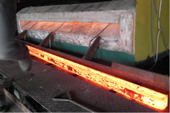
此次采用烧结或喷涂钨坩埚发热体,通过感应加热使钼坩埚发热,然后对需加热的材料进行加热。
7、耐火材料
感应器与钨坩埚之间的耐火材料由三氧化二铝和氧化锆组成。内层由于紧靠钨坩埚,温度较高,所以选用耐火度为2600℃的氧化锆为耐火材料。外层由于有氧化锆为耐火材料的隔热作用,温度较底,所以选用耐火度较低,熔点为2050℃的三氧化二铝为耐火材料即可。这样,既可达到耐火隔热作用,又可以适当地降低烧结炉造价。
现我方经过计算和使用实验,我方把选用的耐火材料(锆砖和铝砖)的厚度都加厚了(锆砖厚40mm,铝砖厚30mm),这样就可以适度的降低能损耗。原理是:经我方对我使用客户的烧结炉维护回访,发现烧结温度提升需最大功率的时候是在高温区,主要是因为高温区的热损失最大。功率大部分叫热损失带走了。现在我方把耐火材料的厚度加厚,虽然烧结炉的成本有所增加,但可以节省很大的能耗,从长远利益来说是绝对合算的。相应的我方的中频电源功率可以相应的选择比较小,只用250KW就完全够用了


First, the composition of the sintering furnace
The working mode of the sintering furnace is intermittent operation of the lower charging. The sintering furnace is mainly composed of a thyristor intermediate frequency power supply, a hydrogen sintering furnace (tank, refractory material, molybdenum crucible, etc.) and an automatic temperature control system.
1. The thyristor intermediate frequency power supply consists of KGPS-250/2.5 250KW 2.5KHz power supply cabinet, electric heating capacitor cabinet, connecting copper bars and engine mechanism;
2. The sintering furnace is composed of a tank body, an inductor, an alumina, a zirconia refractory material, a tungsten crucible, an open return water tank, a hydrogen/nitrogen flow regulating valve control board, a gantry, a lower loading mechanism, and a removal rail;
3. The temperature automatic control system is measured by the Wre5-26 thermocouple and fiber optic sensor, controlled by a temperature regulator, and the temperature is recorded by a paperless recorder. The entire control system is mounted on a vertical operating console for control.
Second, the main technical indicators
1. Inner diameter: φ380 (inside diameter) × 600
2, intrinsic material: sintered tungsten or sprayed tungsten
3. Sintering maximum temperature: 2300 °C
4, temperature control accuracy: ± 10 ° C
5, the working temperature rise of the shell: less than 50 ° C
6, working frequency: 2500Hz
7. Automatic temperature measurement, control, display, automatic recording and storage.
8. The hydrogen protection in the furnace, the flow rate can be adjusted, and the outlet is equipped with slag discharge.
9, hydrogen consumption: 2 cubic meters / hour
10, with overcurrent, overvoltage, phase loss, water pressure, over temperature, power failure protection
11. The loading and unloading mechanism runs smoothly up and down. When loading a workpiece with a height of 1000mm, the highest point swing is no more than 5mm.
12. The maximum speed of the furnace is 15mm/sec, and the loading speed of the loading platform is 45mm/sec.
13. Number of sintering furnaces 1 set
Third, the working process of the sintering furnace:
The workpiece is placed on the tray, and the geared motor drives the tray to move along the removal rail to the lower center position of the tank through the screw, and connects the tray and the lifting mechanism through the positioning pin, and then the brake motor is started, and the two are driven by the gear worm reducer and the steering box. The root screw, the tray is raised upward, and the cone of the tank is connected to the tank body; after the connection is completed, the hydrogen filling and the blasting test are performed. After the heating is completed, the step of the workpiece exiting the tank is opposite to the rising. The motor drives the tray to move downward, and the tray is disconnected from the lifting mechanism afterwards, and the transverse motor drives the tray to move along the guide rail, and the whole work is completed.
Fourth, Lifting and removing mechanisms:
Lifting and removing mechanisms use mechanical lifting mechanisms,
4.1 Mechanical lifting and removal mechanism:
The mechanism consists of four supporting columns, four guiding columns and guide sleeves, a gear worm gear reducer, a lead screw, a steering box, a brake motor, a tray, and a working platform.
4.1.1 The lifting mechanism is equipped with a tray, and the brake motor drives the two screws to rotate through the gear worm reducer. The guide sleeve on the screw is connected with the tray to move the tray up and down to achieve the function of loading and unloading.
4.1.2 In order to reduce the impact of the tray during the connection with the tank, a spring buffer structure, a limit switch and a frequency conversion speed regulating mechanism are added in the design;
4.1.3 In order to ensure the smooth progress of the pallet rise and fall, four guide columns and guide bushes are designed in the mechanism, and the guide posts are supported by the four directions, so that the tray can rise and fall more smoothly;
4.1.4 After the tray is lowered to the ground, manually pull out the connecting pin on the tray and the lifting mechanism, and the tray falls onto the removal platform. At this time, the tray is pulled down and pushed by the control of the motor by using the rail mounted horizontally on the ground. Loading and unloading;
4.1.5 The removal of the pallet adopts the motor to drive the screw to move smoothly on the guide rail, and the limit switch is installed on the guide rail to control the moving position of the pallet;
4.1.6 The input and discharge system adopts frequency conversion speed regulation.
4.1.7 The lower flange of the tray is equipped with a silicone rubber sealing ring. When the tray is raised to the uppermost end, it is sealed by a silicone rubber sealing ring. At this time, the self-locking bolts are tightened to prevent air leakage during temperature rise, and the tray flange can be prevented from opening due to malfunction at high temperatures.
4.1.8 Place zirconia and corundum refractory bricks on the tray. The refractory bricks and the upper plate of the tray have air passages to effectively discharge the air.
4.1.9 The zirconia and corundum refractory bricks placed on the pallet are staggered to prevent the high temperature inside the furnace from directly radiating onto the tray.
Fifth, Platform
A guardrail is arranged outside the workbench, and a step ladder and a step ladder on the top of the stove are arranged. The operation table and step ladder are made of patterned steel plate and are non-slip. A gas control box is arranged on the side of the step ladder, and a valve for controlling gas is arranged inside to switch the gas and adjust the flow rate. The gantry is made detachable and separated along the diameter direction of the furnace body, and then the furnace body is placed in position, and then Close the stand and fasten it with bolts.
Hydrogen / nitrogen flow control valve control panel see left
Sixth, heating body
This time, the sintered or sprayed tungsten-rhenium heating element is used to heat the molybdenum crucible by induction heating, and then the material to be heated is heated.
Seventh, refractory materials
The refractory between the inductor and the tungsten crucible consists of aluminum oxide and zirconium oxide. Since the inner layer is close to the tungsten crucible and the temperature is high, the zirconia having a refractoriness of 2600 ° C is selected as the refractory material. Since the outer layer has the heat insulating effect of zirconia as the refractory material and the temperature is lower, the aluminum oxide having a lower refractoriness and a melting point of 2050 ° C can be used as the refractory material. In this way, both the fire and heat insulation effect can be achieved, and the cost of the sintering furnace can be appropriately reduced.
Now we have calculated and used the experiment, we have thickened the thickness of the selected refractory materials (zirconium brick and aluminum brick) (zirconium brick thickness 40mm, aluminum brick thickness 30mm), so that the energy loss can be moderately reduced. The principle is: After we have used our customer's sintering furnace maintenance return visit, we found that the maximum power required for the sintering temperature increase is in the high temperature zone, mainly because the heat loss in the high temperature zone is the largest. Most of the power is called heat loss. Now we thicken the thickness of the refractory material. Although the cost of the sintering furnace has increased, it can save a lot of energy consumption, which is absolutely cost-effective in the long run. Correspondingly, our intermediate frequency power supply can be relatively small, and only 250KW is enough.
手 机:15038554363
