洛阳松导感应加热科技有限公司
联系方式:15038554363
24小时技术热线:15038554363
邮 箱:1390003299@qq.com
厂址:河南省洛阳市洛新工业园区
Technical parameters and process analysis of 0.5 ton melting furnace
1.1 0.5 ton melting furnace use :
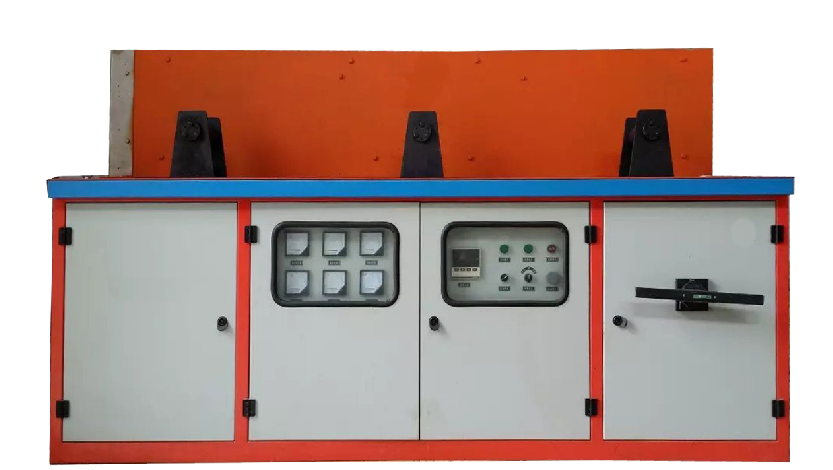
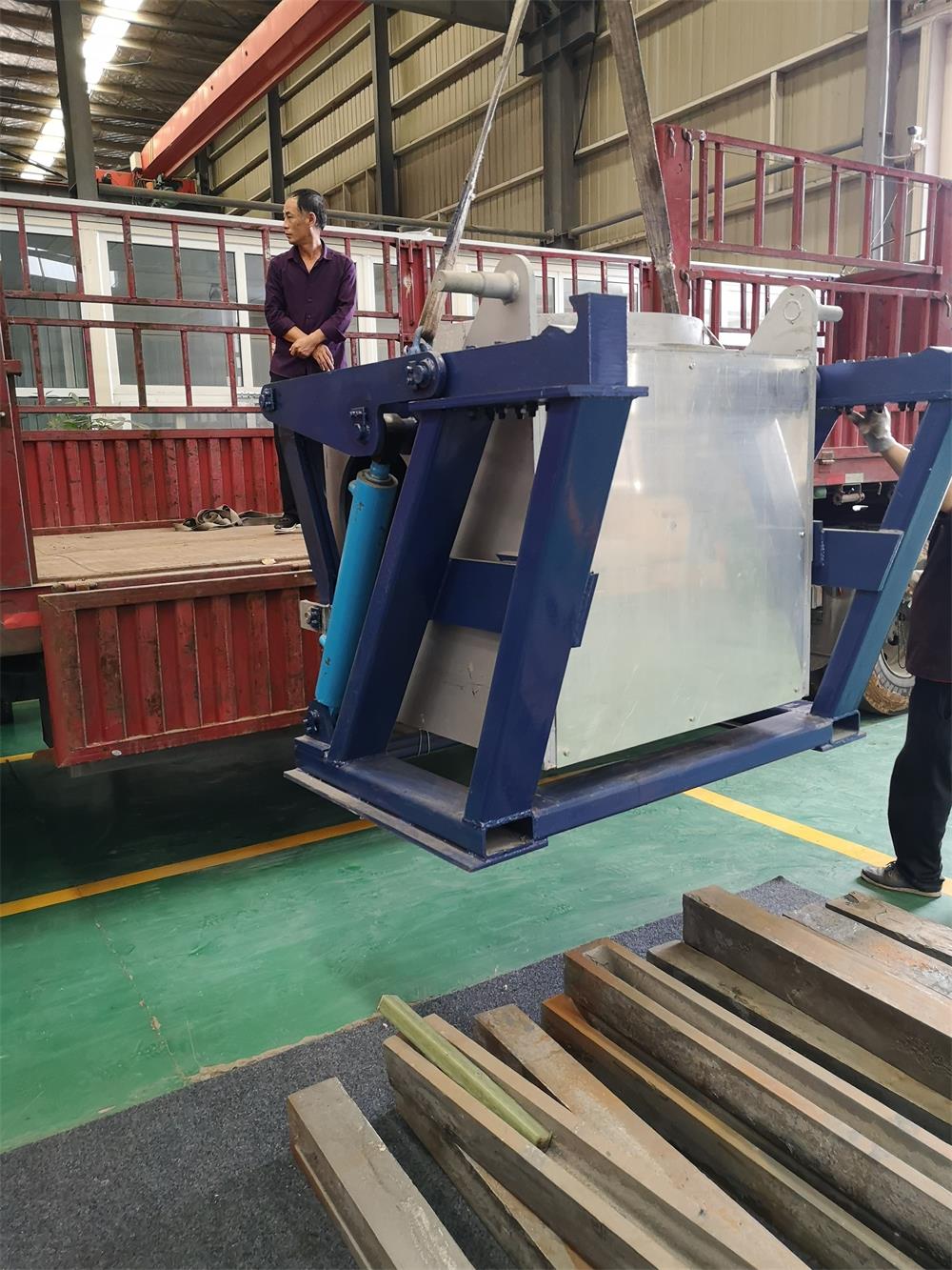
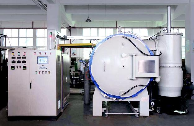
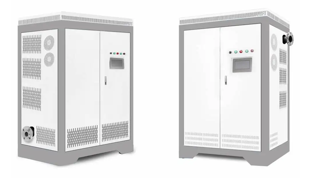
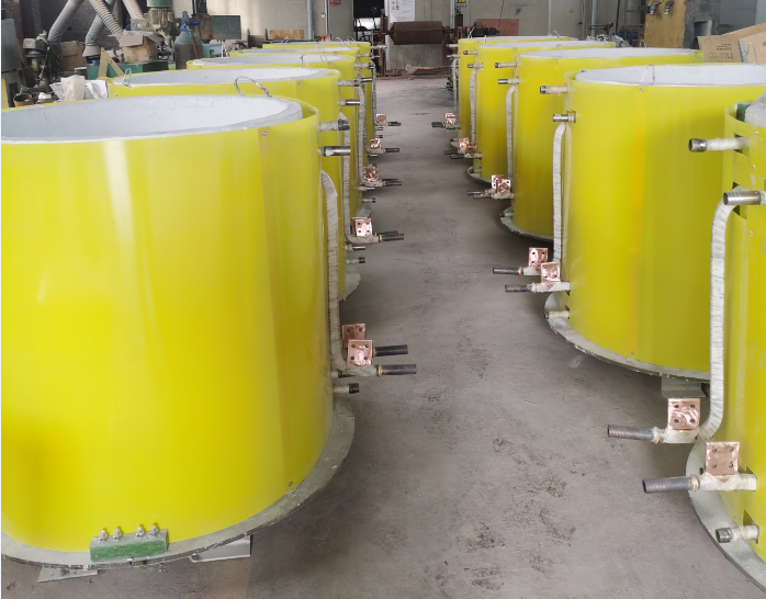
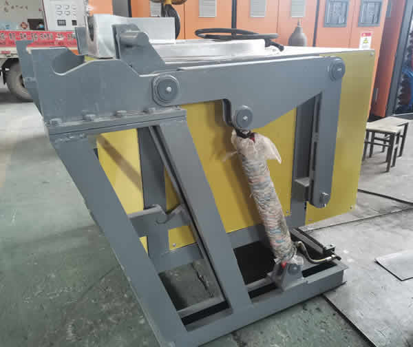
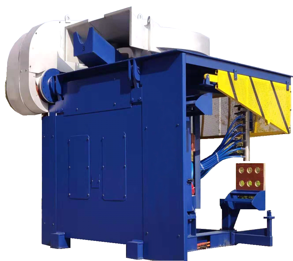
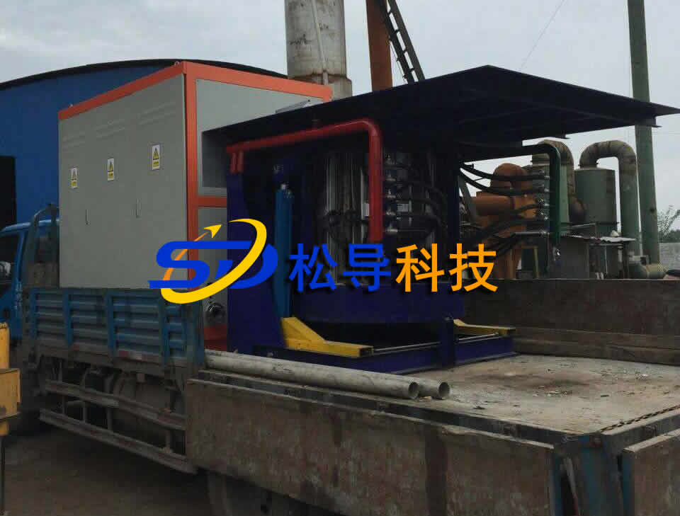
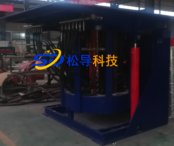
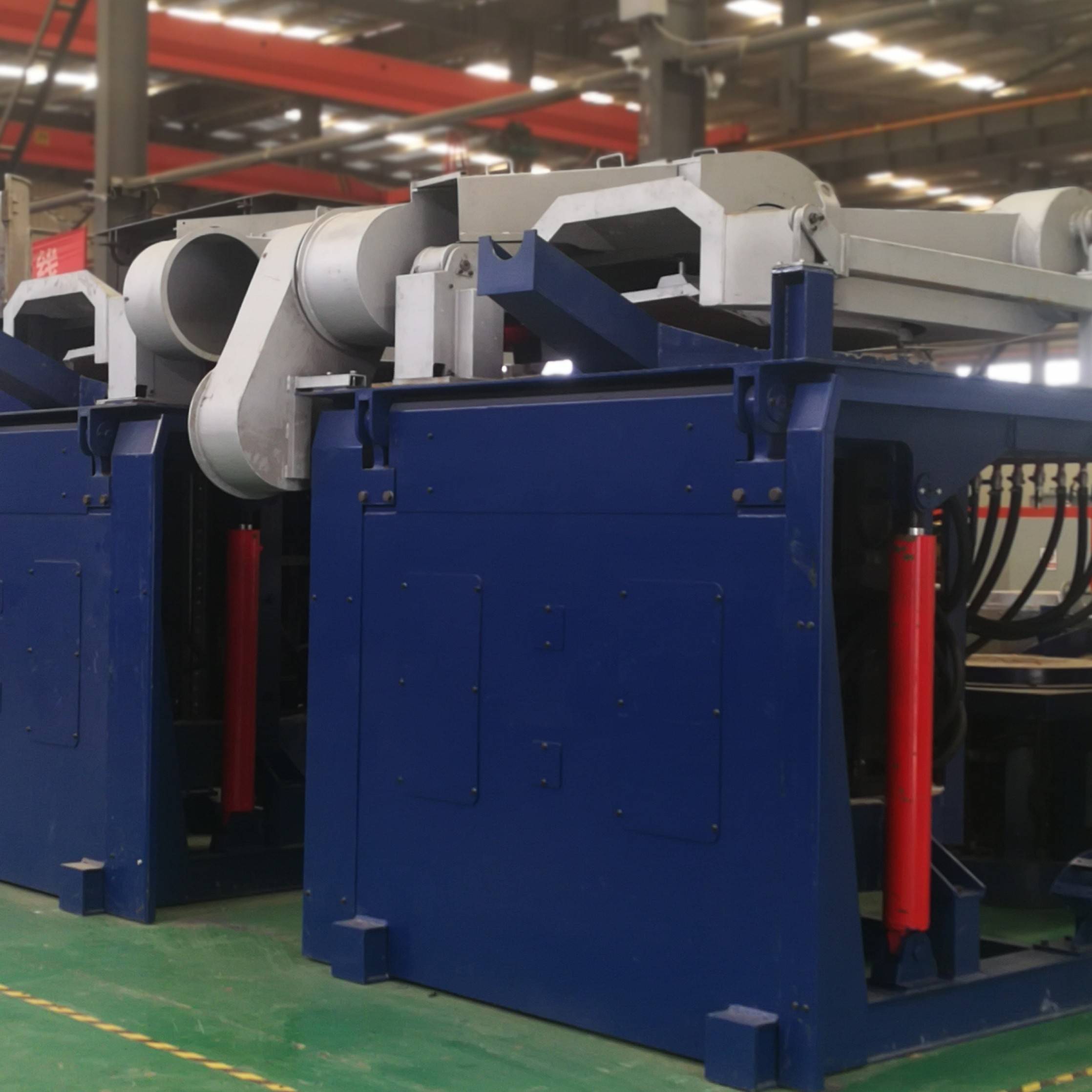
The 0.5 ton melting furnace is an intermediate frequency coreless induction melting furnace for steel smelting in the foundry .
0.5 ton melting furnace power 5 00 KW / 1T equipment.
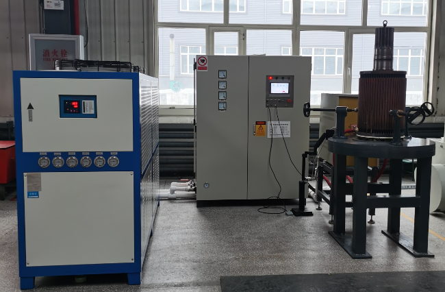
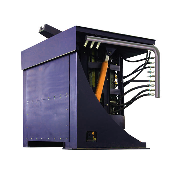
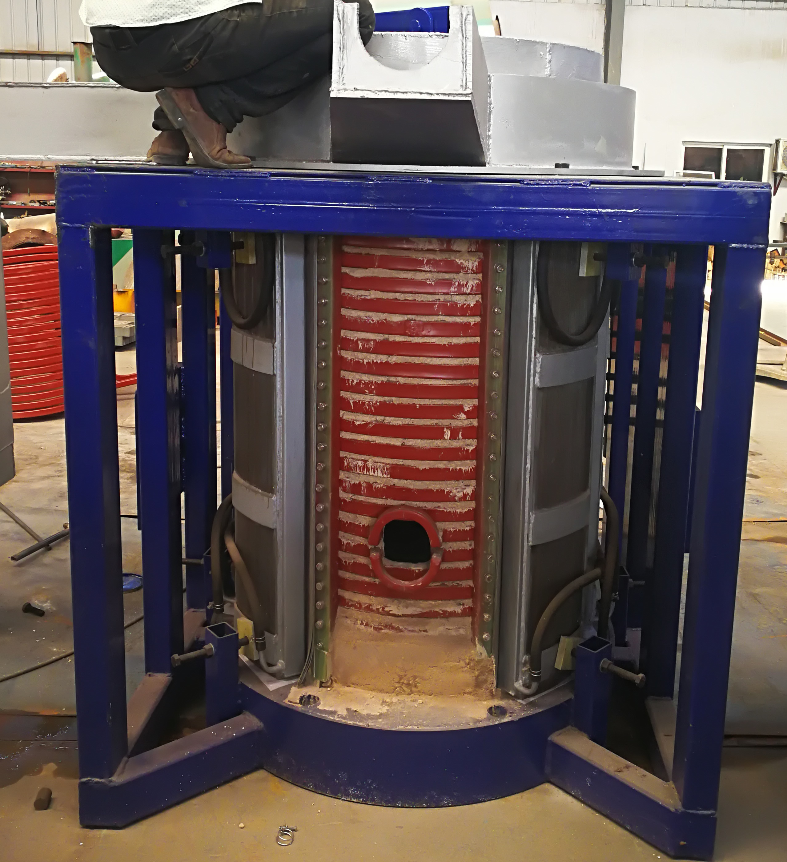
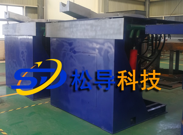
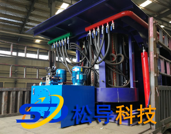
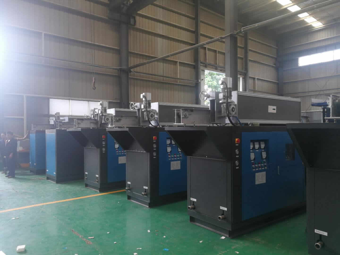
Basic configuration: two furnace bodies, one set of power supply, one set of compensation capacitors, and two sets of furnaces are operated separately. The tilting method is hydraulically reversed with a remote control box.
When designing the equipment, the user's on-site working status is considered to be continuous, and the furnace is frequently discharged. The equipment selection of this scheme ensures the user's output index and meets the user's overall requirements for the equipment: the equipment is durable and performance. Stable, safe and reliable.
1.2 Equipment technical requirements
|
Power rating |
500KW |
|
Power frequency |
1000Hz |
|
Power line voltage |
3×380V |
|
Power factor |
The power factor of the furnace under any power operation is not less than 0.95 |
|
Melting rate |
500KW/1T ≥0.65t/h |
|
Release temperature |
1650 ° C |
|
Power consumption |
≤ 580KW.h/t |
|
Working noise |
<85 decibels |
|
Melting material: |
Cast steel, cast iron |
![]()
1.3 0.5 ton melting furnace smelting description:
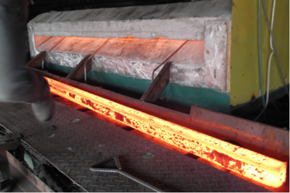
The user's factory uses induction furnace melting, heating, heat preservation, quenching and smelting process.
1.3.1 Power Supply Selection:
In general, the smelting speed and the metal to be smelted are determined in advance. The required melting speed determines the required power. Based on experience, the following estimation principles are available.
The following is the recommended melting furnace rated power configuration (iron and steel)
|
Furnace capacity (T) |
Power range (KW) |
|
0.5-1 |
500-750 |
|
2 |
1000-1500 |
|
3/4 |
1500-2000 |
|
5 |
2000-3000 |
|
6 |
3000-4000 |
|
8 |
4000-5000 |
|
10 |
5000-6000 |
1.3.2 Selection of transformer:
Power supply (KW) × 1.25 = transformer (KVA) Note 1.25 is the safety factor;
1.3.4 Power rectifier design:
In order to reduce the harmonic pollution generated by the high-power IF power supply to the power grid, our company uses the series inverter technology on the intermediate frequency power supply. Therefore, to ensure that the intermediate frequency power supply operates under high power factor, the generated higher harmonics are within the allowable values of the utility grid harmonics specified in the GB/T14549-93 standard;
Comparison of characteristics of parallel and series circuits (table)
|
Project |
Medium frequency power supply type |
|||
|
(a) Parallel type |
(b) tandem type |
(c) series and parallel |
||
|
Output voltage waveform |
Sine wave |
Rectangular wave |
Sine wave |
|
|
Output current waveform |
Rectangular wave |
Sine wave |
Sine wave |
|
|
Induction loop fundamental voltage |
Inverter output voltage |
Q× inverter output voltage |
Inverter output voltage |
|
|
Induction loop fundamental current |
Q× inverter output current |
Inverter output current |
Q× inverter output current |
|
|
DC filter |
Large reactance |
Large capacitance |
Large capacitance |
|
|
Anti-parallel diode |
No need to |
use |
use |
|
|
Thyristor |
Du/dt |
small |
Big |
small |
|
Di/dt |
Big |
small |
|
|
|
Commutation overlap effect |
Series reactance and distributed inductance cause commutation overlap |
no |
|
|
|
Commutation failure protection |
easily |
easily |
easily |
|
|
Additional component |
many |
less |
less |
|
|
effectiveness |
Low (about 90%) |
Normal (about 95%) |
High (90%) |
|
|
Operational stability |
Stable over a wide range |
Stable over a wide range |
Difficult to manufacture below 1000HZ |
|
|
energy saving effect |
difference |
excellent |
difference |
|
Note: The quality factor of the Q-induction loop.
When designing an intermediate frequency induction furnace, the main circuit of the intermediate frequency power supply adopts a series circuit.
The main technical parameters:
|
A. Comprehensive parameters: |
|
|
Equipment form: |
Medium frequency melting furnace |
|
Equipment use: |
Used to smelt steel |
|
Rated Capacity: |
1T 0.75T |
|
Maximum capacity |
2t+10% |
|
Operating temperature: |
1650 ° C (steel) |
|
Smelting material: |
steel |
|
Tilting method: |
Hydraulic control |
|
Maximum angle of the tilting furnace: |
95 degrees |
|
Hydraulic medium: |
Machinery oil |
|
Hydraulic station capacity |
500L |
|
Working pressure: |
11MPa |
|
Working noise: |
<85 decibels |
|
Furnace structure: |
Steel shell |
|
Way out: |
Side outlet |
|
Melting rate: |
500KW/2T ≥0.65t/h |
|
Melting power consumption |
580kW.h/t |
|
B. Electrical parameters: |
|
|
Power supply |
500KW/1T 0.75T |
|
Number of rectifiers |
6 veins |
|
Inverter |
SCR series |
|
Rated frequency |
500Hz |
|
Line voltage |
3×380 |
|
Transformer primary side line voltage |
10KVA |
|
Sensor voltage |
1600V |
|
Start success rate |
100% |
|
Power factor |
Greater than 0.95 |
|
C. Closed cooling tower: |
|
|
Inlet pressure |
0.2-0.4MPa |
|
Inlet temperature |
5-35 ° C |
|
Effluent temperature |
<55°C |
|
Cooling water flow |
40mm 2 |
|
Equipment shape |
2300mm*1200mm*2800mm |
|
Water pump |
5.5KW one use one |
Description of the control principle of the 0.5 ton melting furnace :
Brief description of the operation of 0.5 ton melting furnace :
Waterway operation:
a. Before starting the machine, first check whether the valves of each waterway are open. Before starting the machine, first turn on the cooling water system.
b. Open the external circulating water system first, and observe whether the water pressure and temperature meet the requirements;
c. Open the inner circulating water system again, and observe whether the water pressure and temperature meet the requirements. If it does not meet the requirements, adjust it in time;
d. After all the cooling water is in normal circulation, the electric furnace can be started to smelt;
Control flow chart for intermediate frequency furnace:
0.5 ton melting furnace complete equipment range:
1 equipment range list :
|
Serial number |
Device item name |
Specification model |
unit |
Quantity |
Remarks |
|
1 |
Intermediate frequency power supply |
KGPS-500/1 |
station |
1 |
|
|
2 |
Furnace body |
GW-1 GW-0.5 |
station |
2
|
Leaky furnace alarm |
|
3 |
Hydraulic system |
10Mpa |
set |
2 |
|
|
4 |
Model |
1T 0.5T |
only |
1
|
5mm |
|
5 |
Compensation capacitor cabinet |
KGPS-500/1
|
set |
2
|
Includes: channel busbar |
|
6 |
Furnace front console |
LTL-C1 |
station |
2 |
Includes: three color lights |
|
7 |
Leakage alarm system |
LT-BU-101 |
set |
2 |
Contains: electrode for furnace body |
|
8 |
Water cooled cable |
SL-500 |
set |
2 |
A total of 2 400 square |
|
9 |
Pair of flanges, seals, connecting bolts, feet |
|
set |
1 |
|
XI. Main components supporting manufacturers and quotations:
|
Serial number |
item name |
Place of production |
|
1 |
switch |
Shanghai People's Electric Appliance Factory |
|
2 |
Rectifier thyristor |
Hubei Xiangfan Instrument Component Factory |
|
3 |
Inverter thyristor |
British Sima (domestic package) |
|
4 |
Power meter voltmeter, frequency meter ammeter |
Suzhou Instrument Research Institute |
|
5 |
Capacitor |
Shangyu Capacitor Factory |
|
6 |
main control board |
self made |
|
7 |
Reactor |
self made |
|
8 |
Button, switch, indicator |
Zhengtai |
|
9 |
Wire loop |
Luoyang Copper Material Factory Cold Extrusion Copper Tube T2 Copper |
|
10 |
Yoke (with water cooling) |
Gao Xi silicon steel sheet yoke |
手 机:15038554363
